TECHNOLOGY
Underground Pumped Storage Hydroelectric Technology
Using the proven energy storage method of pumped storage hydroelectric, with salt dome caverns, allows us to create the long duration energy storage that is needed.
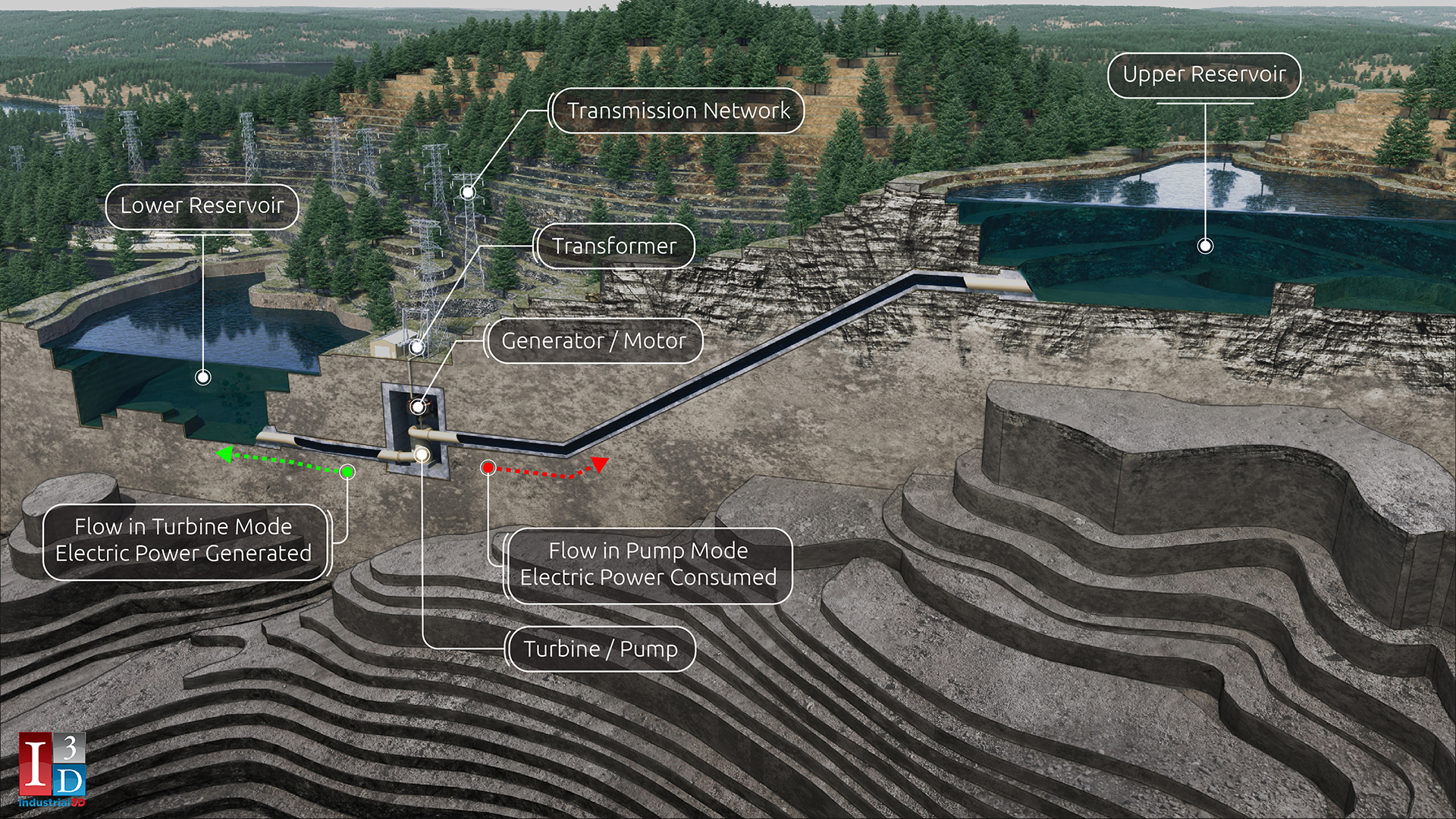
Conventional Pumped Storage Hydroelectric
Conventional pumped storage hydroelectric is the backbone of America’s electricity storage, conventional pumped storage hydroelectric accounts for 94% of the country’s actual electrical energy storage with 23 GW currently installed.
But this technology is limited. You need an area where you can build large water storage reservoirs with considerable height difference between them. As a result, conventional pumped storage hydroelectric is not feasible in relatively flat areas—like US Gulf Coast states.
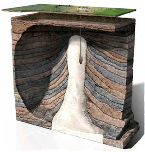
Salt Domes
Salt domes are massive underground structures of plain, normal salt. Since the 1960s, companies have been solution mining the salt and creating caverns for storing oil, natural gas, and other fluids.
As part of its Strategic Petroleum Reserve initiative, the Department of Energy stores oil in salt dome caverns at four locations on the US Gulf Coast—two in Texas and two in Louisiana.
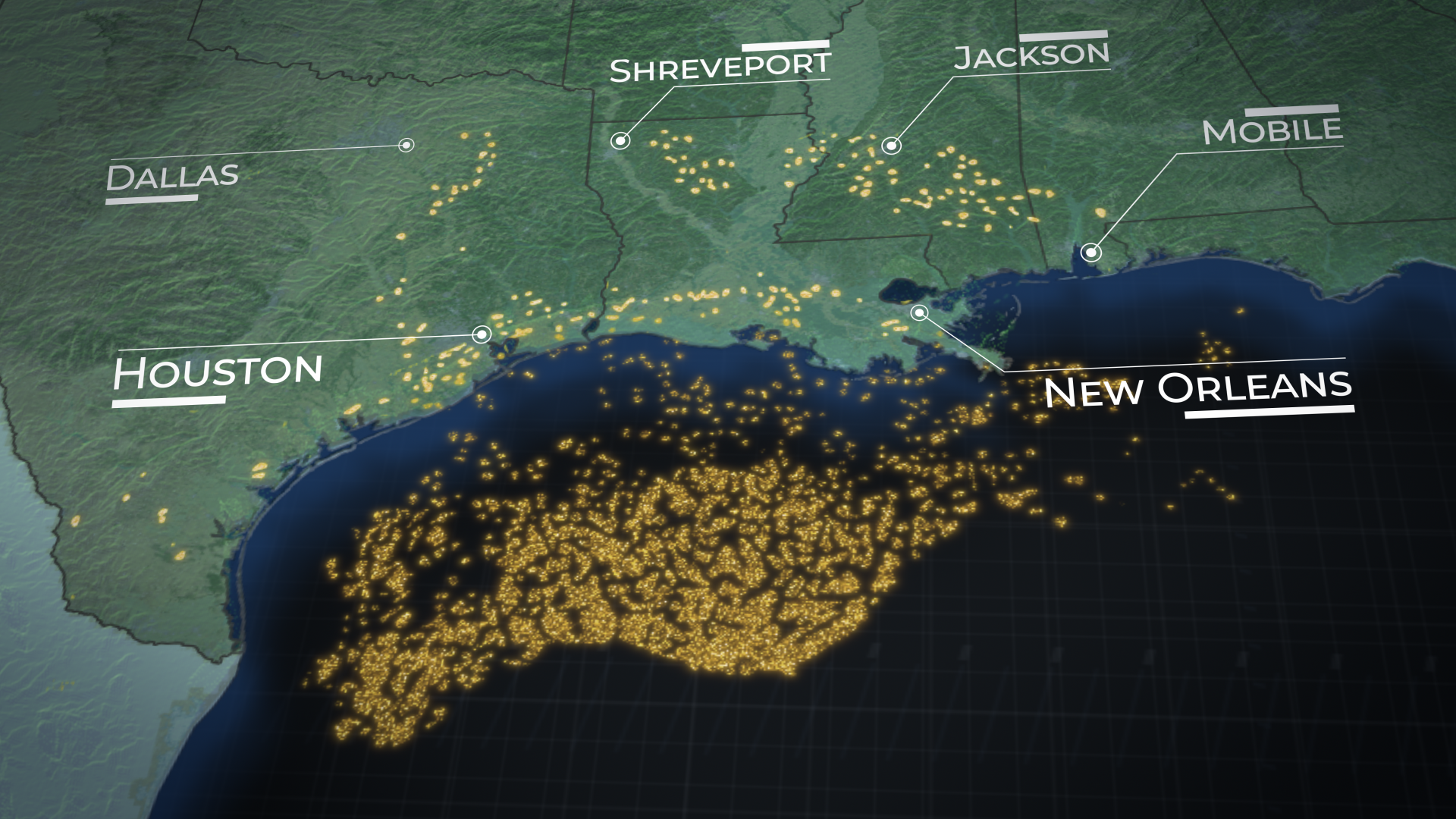
Southern United States Salt Dome Locations
Salt domes are prevalent in Texas, Louisiana, and Mississippi. More than 25 million Americans live in the area where these salt domes exist. The Department of Energy estimates this area needs more than 75 GW of energy storage, but the region is too flat to use conventional pumped storage.
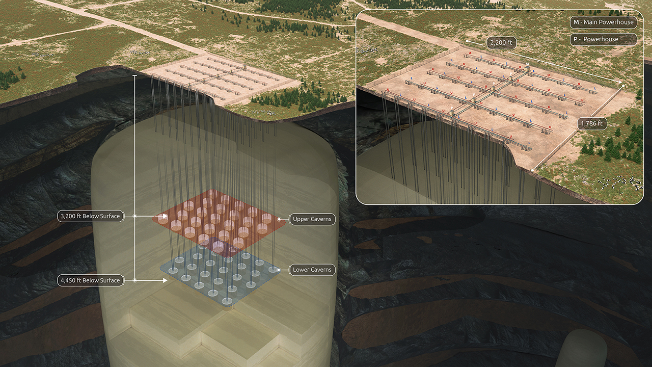
How It Works
Caverns are created in the salt dome at different elevations using the proven techniques of solution mining. The extracted salt is provided to customers who process it into table salt or break it down into sodium and chlorine for other uses. The central well bore in the lower caverns is tied together into a header for the low-pressure side of the pump/turbine. The central well bore in the upper caverns is tied together into a high-pressure header. The wellbore annuluses for both the upper and lower caverns are tied together to form the compressed air header.
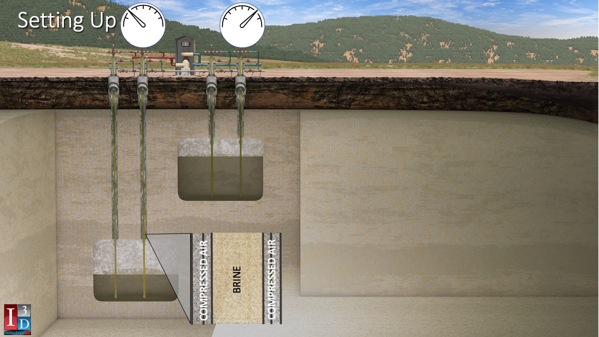
Setting Up
- Compressed air is added to both caverns
- Raising the surface pressure in the brine lines
~60 psig on the lower cavern header
~680 psig on the upper cavern header - For the pump/turbine, this looks exactly like a conventional pumped storage
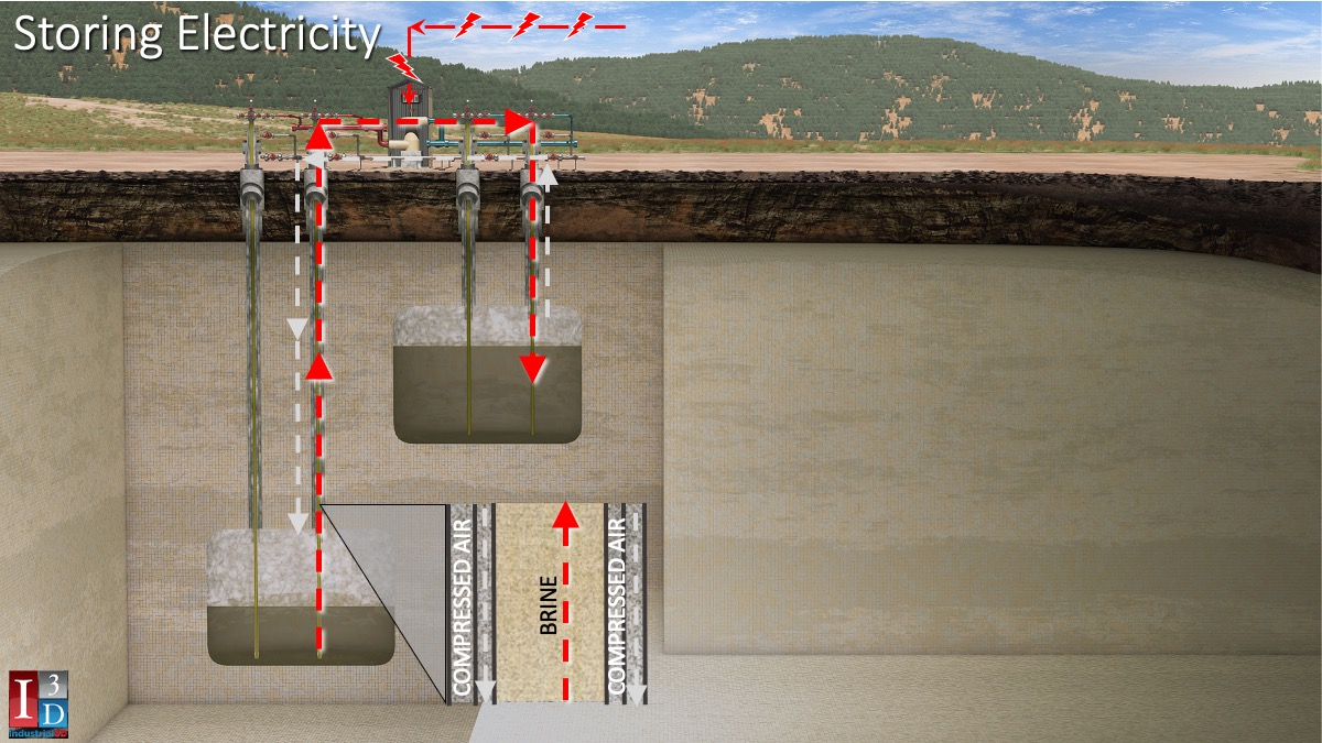
Storing Electricity
- To store electricity – brine is pumped from lower to upper reservoir
- Compressed air freely flows from the upper reservoir to the lower reservoir
- To store 50 MWh of electricity, 290,000 barrels of brine is moved 1250 feet upwards between caverns
Setting Up
- Compressed air is added to both caverns
- Raising the surface pressure in the brine lines
~60 psig on the lower cavern header
~680 psig on the upper cavern header - For the pump/turbine, this looks exactly like a conventional pumped storage
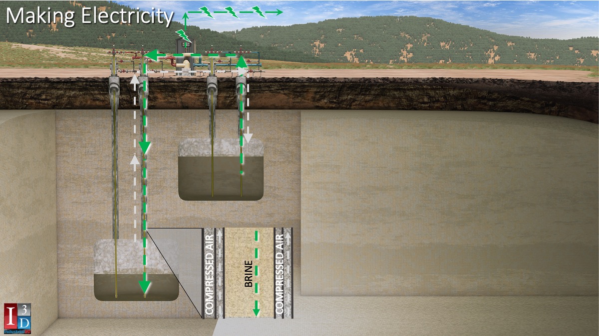
Making Electricity
- To retrieve electricty – brine flows through a hydroelectric turbine from upper to lower reservoir
- Compressed air freely flows the other way from the lower reservoir to the upper reservoir
Large Commerical-Sized Units
Surface area can be used for ranching and other activities (solar panels, wind farms, etc.)
125-MW capacity / 1,500-MWh energy storage
25 lower- and 25 upper-level caverns
Cost competitive with other grid-scale systems
90 acres of salt dome required